January
29
October
18
Ubuntu: Bond two network cards together
Bonding, also called port trunking or link aggregation means combining several network interfaces (NICs) to a single link, providing either high-availability, load-balancing, maximum throughput, or a combination of these.
In this example you will first need to disable Network Manager if you are currently using it.
sudo systemctl stop NetworkManager.service
sudo systemctl disable NetworkManager.service
Installation
sudo apt-get install ifenslave
Interface Configuration
Step 1: Ensure kernel support
Before Ubuntu can configure your network cards into a NIC bond, you need to ensure that the correct kernel module bonding is present, and loaded at boot time.
Edit your /etc/modules configuration:
sudo vi /etc/modules
Ensure that the bonding module is loaded:
# /etc/modules: kernel modules to load at boot time.
#
# This file contains the names of kernel modules that should be loaded
# at boot time, one per line. Lines beginning with “#” are ignored.
loop
lp
rtc
bonding
Step 2: Configure network interfaces
Ensure that your network is brought down:
sudo stop networking
Then load the bonding kernel module:
sudo modprobe bonding
Now you are ready to configure your NICs.
A general guideline is to:
Pick which available NICs will be part of the bond.
Configure all other NICs as usual
Configure all bonded NICs:
To be manually configured
To join the named bond-master
Configure the bond NIC as if it were a normal NIC
Add bonding-specific parameters to the bond NIC as follows.
Edit your interfaces configuration:
sudo vi /etc/network/interfaces
For example, to combine eth0 and eth1 as slaves to the bonding interface bond0 using a simple active-backup setup, with eth0 being the primary interface:
#eth0 is manually configured, and slave to the “bond0” bonded NIC
auto eth0
iface eth0 inet manual
bond-master bond0
bond-primary eth0
#eth1 ditto, thus creating a 2-link bond.
auto eth1
iface eth1 inet manual
bond-master bond0
# bond0 is the bonding NIC and can be used like any other normal NIC.
# bond0 is configured using static network information.
auto bond0
iface bond0 inet static
address 192.168.1.10
gateway 192.168.1.1
netmask 255.255.255.0
bond-mode active-backup
bond-miimon 100
bond-slaves none
The bond-primary directive, if needed, needs to be part of the slave description (eth0 in the example), instead of the master. Otherwise it will be ignored.
As another example, to combine eth0 and eth1 using the IEEE 802.3ad LACP bonding protocol:
#eth0 is manually configured, and slave to the “bond0” bonded NIC
auto eth0
iface eth0 inet manual
bond-master bond0
#eth1 ditto, thus creating a 2-link bond.
auto eth1
iface eth1 inet manual
bond-master bond0
# bond0 is the bonded NIC and can be used like any other normal NIC.
# bond0 is configured using static network information.
auto bond0
iface bond0 inet static
address 192.168.1.10
gateway 192.168.1.1
netmask 255.255.255.0
# bond0 uses standard IEEE 802.3ad LACP bonding protocol
bond-mode 4
bond-miimon 100
bond-lacp-rate 1
bond-slaves eth0 eth1
For bonding-specific networking options please consult the documentation available at BondingModuleDocumentation.
Finally, bring up your network again:
sudo start networking
Checking the bonding interface
Link information is available under /proc/net/bonding/. To check bond0 for example:
# cat /proc/net/bonding/bond0
Ethernet Channel Bonding Driver: v3.5.0 (November 4, 2008)
Bonding Mode: IEEE 802.3ad Dynamic link aggregation
Transmit Hash Policy: layer2 (0)
MII Status: up
MII Polling Interval (ms): 100
Up Delay (ms): 0
Down Delay (ms): 0
802.3ad info
LACP rate: fast
Aggregator selection policy (ad_select): stable
bond bond0 has no active aggregator
Slave Interface: eth1
MII Status: up
Link Failure Count: 0
Permanent HW addr: 00:0c:29:f5:b7:11
Aggregator ID: N/A
Slave Interface: eth2
MII Status: up
Link Failure Count: 0
Permanent HW addr: 00:0c:29:f5:b7:1b
Aggregator ID: N/A
Bringing up/down bonding interface
To bring the bonding interface, run
ifup bond0
To bring down a bonding interface, run
ifdown bond0
Ethernet Bonding modes
Ethernet bonding has different modes you can use. You specify the mode for your bonding interface in /etc/network/interfaces. For example:
bond-mode active-backup
Descriptions of bonding modes
Mode 0
balance-rr
Round-robin policy: Transmit packets in sequential order from the first available slave through the last. This mode provides load balancing and fault tolerance.
Mode 1
active-backup
Active-backup policy: Only one slave in the bond is active. A different slave becomes active if, and only if, the active slave fails. The bond’s MAC address is externally visible on only one port (network adapter) to avoid confusing the switch. This mode provides fault tolerance. The primary option affects the behavior of this mode.
Mode 2
balance-xor
XOR policy: Transmit based on selectable hashing algorithm. The default policy is a simple source+destination MAC address algorithm. Alternate transmit policies may be selected via the xmit_hash_policy option, described below. This mode provides load balancing and fault tolerance.
Mode 3
broadcast
Broadcast policy: transmits everything on all slave interfaces. This mode provides fault tolerance.
Mode 4
802.3ad
IEEE 802.3ad Dynamic link aggregation. Creates aggregation groups that share the same speed and duplex settings. Utilizes all slaves in the active aggregator according to the 802.3ad specification.
Prerequisites:
Ethtool support in the base drivers for retrieving the speed and duplex of each slave.
A switch that supports IEEE 802.3ad Dynamic link aggregation. Most switches will require some type of configuration to enable 802.3ad mode.
Mode 5
balance-tlb
Adaptive transmit load balancing: channel bonding that does not require any special switch support. The outgoing traffic is distributed according to the current load (computed relative to the speed) on each slave. Incoming traffic is received by the current slave. If the receiving slave fails, another slave takes over the MAC address of the failed receiving slave.
Prerequisites:
Ethtool support in the base drivers for retrieving the speed of each slave.
Mode 6
balance-alb
Adaptive load balancing: includes balance-tlb plus receive load balancing (rlb) for IPV4 traffic, and does not require any special switch support. The receive load balancing is achieved by ARP negotiation. The bonding driver intercepts the ARP Replies sent by the local system on their way out and overwrites the source hardware address with the unique hardware address of one of the slaves in the bond such that different peers use different hardware addresses for the server.
Descriptions of balancing algorithm modes
The balancing algorithm is set with the xmit_hash_policy option.
Possible values are:
layer2 Uses XOR of hardware MAC addresses to generate the hash. This algorithm will place all traffic to a particular network peer on the same slave.
layer2+3 Uses XOR of hardware MAC addresses and IP addresses to generate the hash. This algorithm will place all traffic to a particular network peer on the same slave.
layer3+4 This policy uses upper layer protocol information, when available, to generate the hash. This allows for traffic to a particular network peer to span multiple slaves, although a single connection will not span multiple slaves.
encap2+3 This policy uses the same formula as layer2+3 but it relies on skb_flow_dissect to obtain the header fields which might result in the use of inner headers if an encapsulation protocol is used.
encap3+4 This policy uses the same formula as layer3+4 but it relies on skb_flow_dissect to obtain the header fields which might result in the use of inner headers if an encapsulation protocol is used.
The default value is layer2. This option was added in bonding version 2.6.3. In earlier versions of bonding, this parameter does not exist, and the layer2 policy is the only policy. The layer2+3 value was added for bonding version 3.2.2.
By: B Quigley – ubuntu.com
March
31
Networking: Cisco CLI command to display what is connected/wwn on a port
show flogi database
—————————————————————————
INTERFACE VSAN FCID PORT NAME NODE NAME
—————————————————————————
fc1/1 20 0x4a0203 50:05:07:00:00:00:00:00:00:00:00:00:00:00:11:e4
fc1/2 10 0x0a0104 10:00:00:00:00:00:00:00:00:00:00:00:00:00:78:21
fc1/3 20 0x4a0202 10:00:00:00:00:00:00:00:00:00:00:00:00:00:78:61
fc1/5 10 0x0a0102 50:05:07:00:00:00:00:00:00:00:00:00:00:00:11:e4
fc1/9 20 0x4a0201 50:05:07:00:00:00:00:00:00:00:00:00:00:00:11:e6
fc1/13 10 0x0a0106 50:05:07:00:00:00:00:00:00:00:00:00:00:00:11:e6
October
26
Cisco: Configuring the Switch with the CLI-Based Setup Program
Configuring the Switch with the CLI-Based Setup Program
This appendix provides a CLI-based setup procedure for a Catalyst 2960-S standalone switch or a switch stack. Before you turn on the switch power, review the safety warnings in Chapter 2 “Switch Installation.”
Accessing the CLI Through Express Setup
You can access the CLI on an unconfigured switch. Set the switch in Express Setup mode and connect a switch Ethernet port to an Ethernet port on your PC or workstation. Follow the steps described in the getting started guide for turning on the switch and using Express Setup.
When the switch is in Express Setup mode, open a Telnet session to the switch by entering the IP address 10.0.0.1. Enter the setup user EXEC command. Enter the information described in the “IP Settings” section and the “Completing the Setup Program” section.
After you have entered the configuration information for the switch, save it to flash memory by using the write memory privileged EXEC command.

Note ![]() In Express Setup mode, the IP address 10.0.0.1 remains active on the switch until you enter the write memory command. You lose the Telnet connection after entering the write memory command.
In Express Setup mode, the IP address 10.0.0.1 remains active on the switch until you enter the write memory command. You lose the Telnet connection after entering the write memory command.
For information about using the CLI, see the switch command reference for this release.
Accessing the CLI Through the Console Port
You can access the CLI on a configured or unconfigured switch by connecting the RJ-45 console port or USB console port of the switch to your PC or workstation and accessing the switch through a terminal emulation program.
Note ![]() If you have stacked your switches, connect to the console port of one of the switches in the stack. You can initially configure the entire stack from any member switch.
If you have stacked your switches, connect to the console port of one of the switches in the stack. You can initially configure the entire stack from any member switch.
Connecting the RJ-45 Console Port or USB Console Port
Step 1 ![]() If you are connecting the switch USB console port to a Windows-based PC for the first time, install the USB driver according to these instructions. See Figure C-1.
If you are connecting the switch USB console port to a Windows-based PC for the first time, install the USB driver according to these instructions. See Figure C-1.
•![]() “Installing the Cisco Microsoft Windows XP USB Driver” section
“Installing the Cisco Microsoft Windows XP USB Driver” section
•![]() “Installing the Cisco Microsoft Windows 2000 USB Driver” section
“Installing the Cisco Microsoft Windows 2000 USB Driver” section
•![]() “Installing the Cisco Microsoft Windows Vista USB Driver” section
“Installing the Cisco Microsoft Windows Vista USB Driver” section
Note ![]() If you do not want to use the switch USB console port, you can use an RJ-45-to-DB-9 adapter cable to connect the switch RJ-45 console port to a PC or terminal port.
If you do not want to use the switch USB console port, you can use an RJ-45-to-DB-9 adapter cable to connect the switch RJ-45 console port to a PC or terminal port.
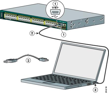
Figure C-1 Connecting the USB Console Cable to the Catalyst 2960-S Switch
|
1
|
USB console port (5-pin mini-Type B) |
|
2
|
USB Type A to 5-pin mini-Type B cable |
|
3
|
USB Type A connection on laptop |
Step 2 ![]() Start the terminal-emulation program on the PC or the terminal. The program, frequently a PC application such as HyperTerminal or ProcommPlus, makes communication between the switch and your PC or terminal possible.
Start the terminal-emulation program on the PC or the terminal. The program, frequently a PC application such as HyperTerminal or ProcommPlus, makes communication between the switch and your PC or terminal possible.
Step 3 ![]() Configure the baud rate and character format of the PC or terminal to match the console port default characteristics:
Configure the baud rate and character format of the PC or terminal to match the console port default characteristics:
•![]() 9600 baud
9600 baud
•![]() 8 data bits
8 data bits
•![]() 1 stop bit
1 stop bit
•![]() No parity
No parity
•![]() None (flow control)
None (flow control)
Step 4 ![]() Power on the switch as described in the switch getting started guide.
Power on the switch as described in the switch getting started guide.
Step 5 ![]() The PC or terminal displays the bootloader sequence. Press Enter to display the setup prompt. Follow the steps in the “Completing the Setup Program” section.
The PC or terminal displays the bootloader sequence. Press Enter to display the setup prompt. Follow the steps in the “Completing the Setup Program” section.
Installing the Cisco Microsoft Windows USB Device Driver
A USB device driver must be installed the first time a Microsoft Windows-based PC is connected to the switch USB console port.
Installing the Cisco Microsoft Windows XP USB Driver
Step 1 ![]() Obtain the file Cisco_usbconsole_driver.zip from the Cisco.com web site and unzip it.
Obtain the file Cisco_usbconsole_driver.zip from the Cisco.com web site and unzip it.
Note ![]() You can download the driver file from the Cisco.com site where you download the switch software.
You can download the driver file from the Cisco.com site where you download the switch software.
Step 2 ![]() If using 32-bit Windows XP, double-click the file setup.exe from the Windows_32 folder. If using 64-bit Windows XP, double-click the file setup(x64).exe from the Windows_64 folder.
If using 32-bit Windows XP, double-click the file setup.exe from the Windows_32 folder. If using 64-bit Windows XP, double-click the file setup(x64).exe from the Windows_64 folder.
Step 3 ![]() The Cisco Virtual Com InstallShield Wizard begins.
The Cisco Virtual Com InstallShield Wizard begins.
Step 4 ![]() The Ready to Install the Program window appears, Click Install.
The Ready to Install the Program window appears, Click Install.
Step 5 ![]() The InstallShield Wizard Completed window appears. Click Finish.
The InstallShield Wizard Completed window appears. Click Finish.
Step 6 ![]() Connect the USB cable to the PC and switch console port. The LED for the USB console port turns green (see Table 1-10), and within a few seconds a series of Found New Hardware Wizard windows appear. Follow the instructions to complete the driver installation.
Connect the USB cable to the PC and switch console port. The LED for the USB console port turns green (see Table 1-10), and within a few seconds a series of Found New Hardware Wizard windows appear. Follow the instructions to complete the driver installation.
The USB console is ready for use.
Installing the Cisco Microsoft Windows 2000 USB Driver
Step 1 ![]() Obtain the file Cisco_usbconsole_driver.zip from the Cisco.com web site and unzip it.
Obtain the file Cisco_usbconsole_driver.zip from the Cisco.com web site and unzip it.
Note ![]() You can download the driver file from the Cisco.com site where you download the switch software.
You can download the driver file from the Cisco.com site where you download the switch software.
Step 2 ![]() Double-click the file setup.exe.
Double-click the file setup.exe.
Step 3 ![]() The Cisco Virtual Com InstallShield Wizard begins. Click Next.
The Cisco Virtual Com InstallShield Wizard begins. Click Next.
Step 4 ![]() The Ready to Install the Program window appears, Click Install.
The Ready to Install the Program window appears, Click Install.
Step 5 ![]() The InstallShield Wizard Completed window appears. Click Finish.
The InstallShield Wizard Completed window appears. Click Finish.
Step 6 ![]() Connect the USB cable to the PC and switch console port. The LED for the USB console port turns green (see Table 1-10), and within a few seconds a series of Found New Hardware Wizard windows appear. Follow the instructions to complete the driver installation.
Connect the USB cable to the PC and switch console port. The LED for the USB console port turns green (see Table 1-10), and within a few seconds a series of Found New Hardware Wizard windows appear. Follow the instructions to complete the driver installation.
The USB console is ready for use.
Installing the Cisco Microsoft Windows Vista USB Driver
Step 1 ![]() Obtain the file Cisco_usbconsole_driver.zip from the Cisco.com web site and unzip it.
Obtain the file Cisco_usbconsole_driver.zip from the Cisco.com web site and unzip it.
Note ![]() You can download the driver file from the Cisco.com site where you download the switch software.
You can download the driver file from the Cisco.com site where you download the switch software.
Step 2 ![]() If using 32-bit Windows Vista, double-click the file setup.exe from the Windows_32 folder. If using 64-bit Windows Vista, double-click the file setup(x64).exe from the Windows_64 folder.
If using 32-bit Windows Vista, double-click the file setup.exe from the Windows_32 folder. If using 64-bit Windows Vista, double-click the file setup(x64).exe from the Windows_64 folder.
Step 3 ![]() The Cisco Virtual Com InstallShield Wizard begins. Click Next.
The Cisco Virtual Com InstallShield Wizard begins. Click Next.
Step 4 ![]() The Ready to Install the Program window appears, Click Install.
The Ready to Install the Program window appears, Click Install.
Note ![]() If a User Account Control warning appears, click “Allow – I trust this program…” to proceed.
If a User Account Control warning appears, click “Allow – I trust this program…” to proceed.
Step 5 ![]() The InstallShield Wizard Completed window appears. Click Finish.
The InstallShield Wizard Completed window appears. Click Finish.
Step 6 ![]() Connect the USB cable to the PC and the switch console port. The LED for the USB console port turns green (see Table 1-10), and within a few seconds a series of Found New Hardware Wizard windows appear. Follow the instructions to complete the driver installation.
Connect the USB cable to the PC and the switch console port. The LED for the USB console port turns green (see Table 1-10), and within a few seconds a series of Found New Hardware Wizard windows appear. Follow the instructions to complete the driver installation.
The USB console is ready for use.
Uninstalling the Cisco Microsoft Windows USB Driver
Uninstalling the Cisco Microsoft Windows XP and 2000 USB Driver
The driver can be removed using the Windows Add or Remove Programs utility or the setup.exe program.
Using the Add or Remove Programs Utility
Note ![]() Disconnect the switch console terminal before uninstalling the driver.
Disconnect the switch console terminal before uninstalling the driver.
Step 1 ![]() Click Start > Control Panel > Add or Remove Programs.
Click Start > Control Panel > Add or Remove Programs.
Step 2 ![]() Scroll to Cisco Virtual Com and click Remove.
Scroll to Cisco Virtual Com and click Remove.
Step 3 ![]() When the Program Maintenance window appears, select the Remove radio button. Click Next.
When the Program Maintenance window appears, select the Remove radio button. Click Next.
Using the Setup.exe Program
Note ![]() Disconnect the switch console terminal before uninstalling the driver.
Disconnect the switch console terminal before uninstalling the driver.
Step 1 ![]() Run setup.exe for Windows 32-bit or setup(x64).exe for Windows-64bit. Click Next.
Run setup.exe for Windows 32-bit or setup(x64).exe for Windows-64bit. Click Next.
Step 2 ![]() The InstallShield Wizard for Cisco Virtual Com appears. Click Next.
The InstallShield Wizard for Cisco Virtual Com appears. Click Next.
Step 3 ![]() When the Program Maintenance window appears, select the Remove radio button. Click Next.
When the Program Maintenance window appears, select the Remove radio button. Click Next.
Step 4 ![]() When the Remove the Program window appears, click Remove.
When the Remove the Program window appears, click Remove.
Step 5 ![]() When the InstallShield Wizard Completed window appears, click Finish.
When the InstallShield Wizard Completed window appears, click Finish.
Uninstalling the Cisco Microsoft Windows Vista USB Driver
Note ![]() Disconnect the switch console terminal before uninstalling the driver.
Disconnect the switch console terminal before uninstalling the driver.
Step 1 ![]() Run the setup.exe for Windows 32-bit or setup(x64).exe for Windows-64bit. Click Next.
Run the setup.exe for Windows 32-bit or setup(x64).exe for Windows-64bit. Click Next.
Step 2 ![]() The InstallShield Wizard for Cisco Virtual Com appears. Click Next.
The InstallShield Wizard for Cisco Virtual Com appears. Click Next.
Step 3 ![]() When the Program Maintenance window appears, select the Remove radio button. Click Next.
When the Program Maintenance window appears, select the Remove radio button. Click Next.
Step 4 ![]() When the Remove the Program window appears, click Remove.
When the Remove the Program window appears, click Remove.
Step 5 ![]() If a User Account Control warning appears, click “Allow – I trust this program…” to proceed.
If a User Account Control warning appears, click “Allow – I trust this program…” to proceed.
Step 6 ![]() When the InstallShield Wizard Completed window appears, click Finish.
When the InstallShield Wizard Completed window appears, click Finish.
Entering the Initial Configuration Information
To set up the switch, you need to complete the setup program, which runs automatically after the switch is powered on. You must assign an IP address and other configuration information necessary for the switch to communicate with the local routers and the Internet. This information is also needed to use the device manager or Cisco Network Assistant to configure and manage the switch.
IP Settings
Obtain this information from your network administrator before you start the setup program:
•![]() Switch IP address
Switch IP address
•![]() Subnet mask (IP netmask)
Subnet mask (IP netmask)
•![]() Default gateway (router)
Default gateway (router)
•![]() Enable secret password
Enable secret password
•![]() Enable password
Enable password
•![]() Telnet password
Telnet password
Completing the Setup Program
If your switches are stacked and there are multiple console connections to individual switches in the stack, the initial setup dialog appears at the console where you first press Enter.
Step 1 ![]() Enter Yes at these two prompts.
Enter Yes at these two prompts.
Would you like to enter the initial configuration dialog? [yes/no]: yes
At any point you may enter a question mark '?' for help.
Use ctrl-c to abort configuration dialog at any prompt.
Default settings are in square brackets '[]'.
Basic management setup configures only enough connectivity
for management of the system, extended setup will ask you
to configure each interface on the system.
Would you like to enter basic management setup? [yes/no]: yes
Step 2 ![]() Enter a host name for the switch, and press Return.
Enter a host name for the switch, and press Return.
On a command switch, the host name is limited to 28 characters; on a member switch to 31 characters. Do not use -n, where n is a number, as the last character in a host name for any switch.
Enter host name [Switch]: host_name
Step 3 ![]() Enter an enable secret password, and press Return.
Enter an enable secret password, and press Return.
The password can be from 1 to 25 alphanumeric characters, can start with a number, is case sensitive, allows spaces, but ignores leading spaces. The secret password is encrypted, and the enable password is in plain text.
Enter enable secret: secret_password
Step 4 ![]() Enter an enable password, and press Return.
Enter an enable password, and press Return.
Enter enable password: enable_password
Step 5 ![]() Enter a virtual terminal (Telnet) password, and press Return.
Enter a virtual terminal (Telnet) password, and press Return.
The password can be from 1 to 25 alphanumeric characters, is case sensitive, allows spaces, but ignores leading spaces.
Enter virtual terminal password: terminal-password
Step 6 ![]() (Optional) Configure Simple Network Management Protocol (SNMP) by responding to the prompts. You can also configure SNMP later through the CLI, the device manager, or the Network Assistant application. To configure SNMP later, enter no.
(Optional) Configure Simple Network Management Protocol (SNMP) by responding to the prompts. You can also configure SNMP later through the CLI, the device manager, or the Network Assistant application. To configure SNMP later, enter no.
Configure SNMP Network Management? [no]: no
Step 7 ![]() Enter the interface name (physical interface or VLAN name) of the connection to the management network, and press Return. For this release, always use vlan1 as that interface.
Enter the interface name (physical interface or VLAN name) of the connection to the management network, and press Return. For this release, always use vlan1 as that interface.
Enter interface name used to connect to the
management network from the above interface summary: vlan1
Step 8 ![]() Configure the interface by entering the switch IP address and subnet mask and pressing Return. The IP address and subnet masks shown are examples.
Configure the interface by entering the switch IP address and subnet mask and pressing Return. The IP address and subnet masks shown are examples.
Configuring interface vlan1:
Configure IP on this interface? [yes]: yes
IP address for this interface: 10.4.120.106
Subnet mask for this interface [255.0.0.0]: 255.0.0.0
Step 9 ![]() Enter Y to configure the switch as the cluster command switch. Enter N to configure it as a member switch or as a standalone switch.
Enter Y to configure the switch as the cluster command switch. Enter N to configure it as a member switch or as a standalone switch.
If you enter N, the switch appears as a candidate switch in the Network Assistant GUI. You can configure the switch as a command switch later through the CLI, the device manager, or the Network Assistant application. To configure it later, enter no.
Would you like to enable as a cluster command switch? [yes/no]: no
You have now completed the initial configuration of the switch and the switch. This is an example of the configuration output that appears:
The following configuration command script was created:
hostname switch1
enable secret 5 $1$Ulq8$DlA/OiaEbl90WcBPd9cOn1
enable password enable_password
line vty 0 15
password terminal-password
no snmp-server
!
no ip routing
!
interface Vlan1
no shutdown
ip address 10.4.120.106 255.0.0.0
!
interface GigabitEthernet1/0/1
!
interface GigabitEthernet1/0/2
interface GigabitEthernet1/0/3
!
...<output abbreviated>
!
interface GigabitEthernet1/0/23
!
end
Step 10 ![]() These choices appear:
These choices appear:
[0] Go to the IOS command prompt without saving this config.
[1] Return back to the setup without saving this config.
[2] Save this configuration to nvram and exit.
Choose (2) to save the configuration to NVRAM to use it the next time the switch reboots.
Enter your selection [2]:2
Make your selection, and press Return.
August
24
Networking: Ftp Commands
FTP Commands
| ? | to request help or information about the FTP commands |
|
|---|---|---|
| ascii | to set the mode of file transfer to ASCII(this is the default and transmits seven bits per character) |
|
| binary | to set the mode of file transfer to binary(the binary mode transmits all eight bits per byte and thus provides less chance of a transmission error and must be used to transmit files other than ASCII files) |
|
| bye | to exit the FTP environment (same as quit) |
|
| cd | to change directory on the remote machine | |
| close | to terminate a connection with another computer | |
| close brubeck | closes the current FTP connection with brubeck,but still leaves you within the FTP environment. | |
| delete | to delete (remove) a file in the current remote directory (same as rm in UNIX) |
|
| get | to copy one file from the remote machine to the local machine |
|
| get ABC DEF | copies file ABC in the current remote directory to (or on top of) a file named DEF in your current local directory. |
|
| get ABC | copies file ABC in the current remote directory to (or on top of) a file with the same name, ABC, in your current local directory. |
|
| help | to request a list of all available FTP commands |
|
| lcd | to change directory on your local machine (same as UNIX cd) |
|
| ls | to list the names of the files in the current remote directory |
|
| mkdir | to make a new directory within the current remote directory |
|
| mget | to copy multiple files from the remote machine to the local machine;you are prompted for a y/n answer before transferring each filemget: To stop this command from prompting for multiple files. Type: prompt off. |
|
| mget * | copies all the files in the current remote directory to your current local directory, using the same filenames. Notice the use of the wild card character, *. |
|
| mput | to copy multiple files from the local machine to the remote machine;you are prompted for a y/n answer before transferring each file |
|
| open | to open a connection with another computer | |
| open brubeck | opens a new FTP connection with brubeck;you must enter a username and password for a brubeck account(unless it is to be an anonymous connection). |
|
| put | to copy one file from the local machine to the remote machine |
|
| pwd | to find out the pathname of the current directory on the remote machine |
|
| quit | to exit the FTP environment (same as bye) |
|
| rmdir | to to remove (delete) a directory in the current remote directory |
|
By: schauble